Why is there a need for a motor driver circuit?
Normal DC gear-head motors requires current greater than 250mA. ICs like 555 timer, ATmega16 Microcontroller, 74 series ICs cannot supply this amount of current. If we directly connect motors to the output of any of the above IC's, they might get damaged.
There is a need of a circuitry that can act as a bridge between the above mentioned ICs and the motors. There are several ways of making it, some of them are mentioned below.
Using Transistor
Single direction control
If you want to rotate your motor in only one direction, then this is the easiest way to do so. Here power transistor is used as a switch to turn a motor on or off depending upon the applied voltage at base. Its circuit is shown below. The same motor driver circuit is used in making a simple line follower robot.
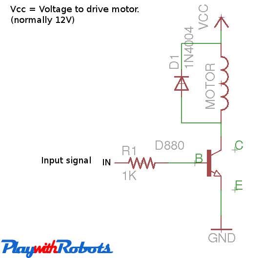
One direction motor control
Working of above circuit
The figure below will describe its working.
Working
Note :
- Check the rating of the transistor you are using. It must be greater than the maximum current drawn by your motor. A normal DC motor as shown below draws 250mA current. D880 transistor has a max collector current rating of 3A.
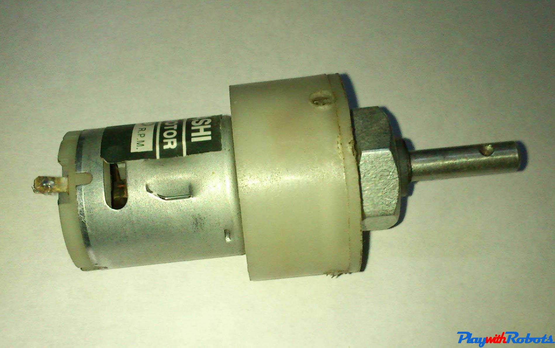
Gear-head motor
- Use power transistors, as chances of their damage is less in case of a short circuit due to the heat sink attached to them.* If the current requirement is higher, then use Relays.
Both direction control ( H-Bridge circuit)
For controlling motor in both directions H bridge circuit is used. Its working is very simple and is described below.
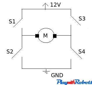
H-bridge working
| Closed Switches | Open Switches | Voltage across motor | Motion |
| Nil | S1,S2,S3,S4 | 0 | No motion |
| S1,S4 | S2,S3 | 12V (say) | Clockwise (say) |
| S2,S3 | S1,S4 | -12V | Anti-clockwise |
| S1,S3 | S2,S4 | 0V | Brake |
So there are four possible conditions out of 16 combinations of the switch that we are working on. This is met by using 2 npn and 2 pnp transistor as shown below.
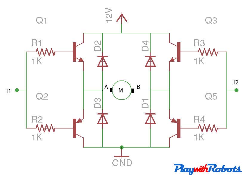
Transistor H-bridge
| I1 | I2 | A | B | Motion |
| Logic 0 | Logic 0 | 0 | 0 | Stop |
| Logic 1 | Logic 0 | 12V | 0 | Clockwise |
| Logic 0 | Logic 1 | 0 | 12V | Anti-clockwise |
| Logic 1 | Logic 1 | 12V | 12V | Brake |
Logic 1 means 5V and Logic 0 means GND. Choose npn and pnp power transistors according to the current requirement of the motor under load.
The above circuit works well but L298/L293D IC's are prefered over them, as they are compact and offer PWM channels to control motor's speed.
Using L293D/L298
L293D and L298 are dual H-bridge motor driver ICs. We can control the rotation of two motors in both clockwise and anti-clockwise direction. The pin-outs of both ICs are shown below along with their differences.
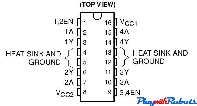
L293D pin configuration
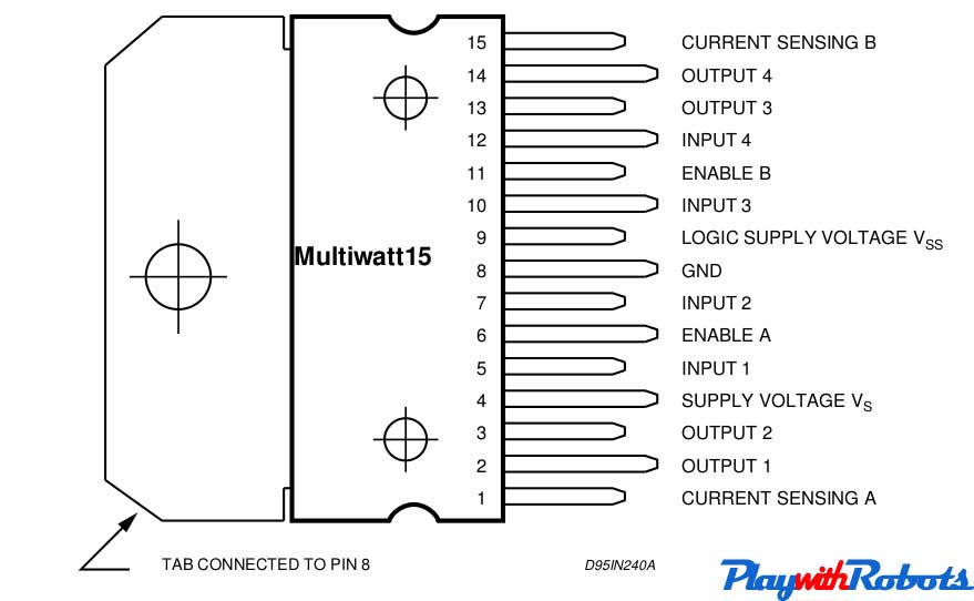
L298 pin configuration
Main difference between L293D and L298
| Characteristic | L298 | L293D |
| Continuous max. output current per channel | 2A | 0.6A |
| Peak max. output current per channel ( <100us) | 3A | 1A |
| Protection diodes across motors | Use externally | Internally available |
Source: L293D and L298 datasheets.
Here we prefer L293D as a rating of 600mA is good for driving small DC motors and protection diodes are included in the IC itself. The description of each pin is as follows:
- Enable pins: These are pin no. 1 and pin no. 9. Pin no. 1 is used to enable Half-H driver 1 and 2.( H bridge on Left side). Pin no. 9 is used to enable H-bridge driver 3and 4.(H bridge on right side). The concept is simple, if you want to use a particular H bridge you have to give a high logic to corresponding enable pins along with the power supply to the IC. This pin can also be used to control speed of the motor using PWM technique.
- VCC1 (Pin 16): Power supply pin. Connect it to 5V supply.
- VCC2 (Pin 8): Power supply for motor. Apply +ve voltage to it as per motor rating. If you want to drive your motor at 12V, apply 12V on this pin. It is also possible to drive motor directly on a battery, other than the one used for supplying power to the circuit, Just connect +ve terminal of that battery to VCC2 pin and make GND of both the batteries common. (MAX voltage at this pin is 36V as per its datasheet).
- GND (Pins 4,5,12,13): Connect them to common GND of circuit.
- Inputs (Pins 2,7,10,15): These are input pins through which control signals are given by microcontrollers or other circuits/ICs. For example, if on pin 2 (Input of 1st half H driver) we give Logic 1 ( 5V), we will get a voltage equal to VCC2 on corresponding output pin of 1st half H driver i.e pin no. 3. Similarly for Logic 0 (0V) on Pin 2, 0V on Pin 3 appears.
- Outputs ( Pin 3,6,11,14): Outputs pins. According to input signal output signal comes.
Circuit diagram :
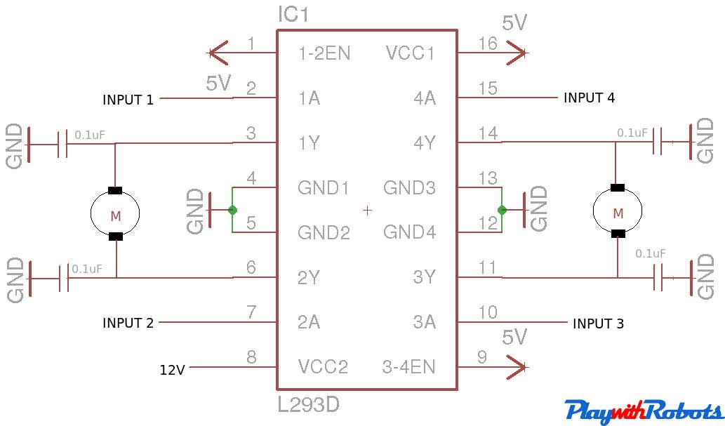
Circuit diagram
| 1A | 2A | 1Y | 2Y | Motor 1 |
| Logic 0 | Logic 0 | 0 | 0 | Stop |
| Logic 1 | Logic 0 | 12V | 0 | Clockwise |
| Logic 0 | Logic 1 | 0 | 12V | Anti-clockwise |
| Logic 1 | Logic 1 | 12V | 12V | Brake |
For driving high power motors relays are used like cars Wiper motor.
Using Relays
Relays are electromechanical switches. They have very high current rating and both AC and DC motors can be controlled through them because motor will be completely isolated from the remaining circuit. Two common available SPDT relays are shown in the picture below.
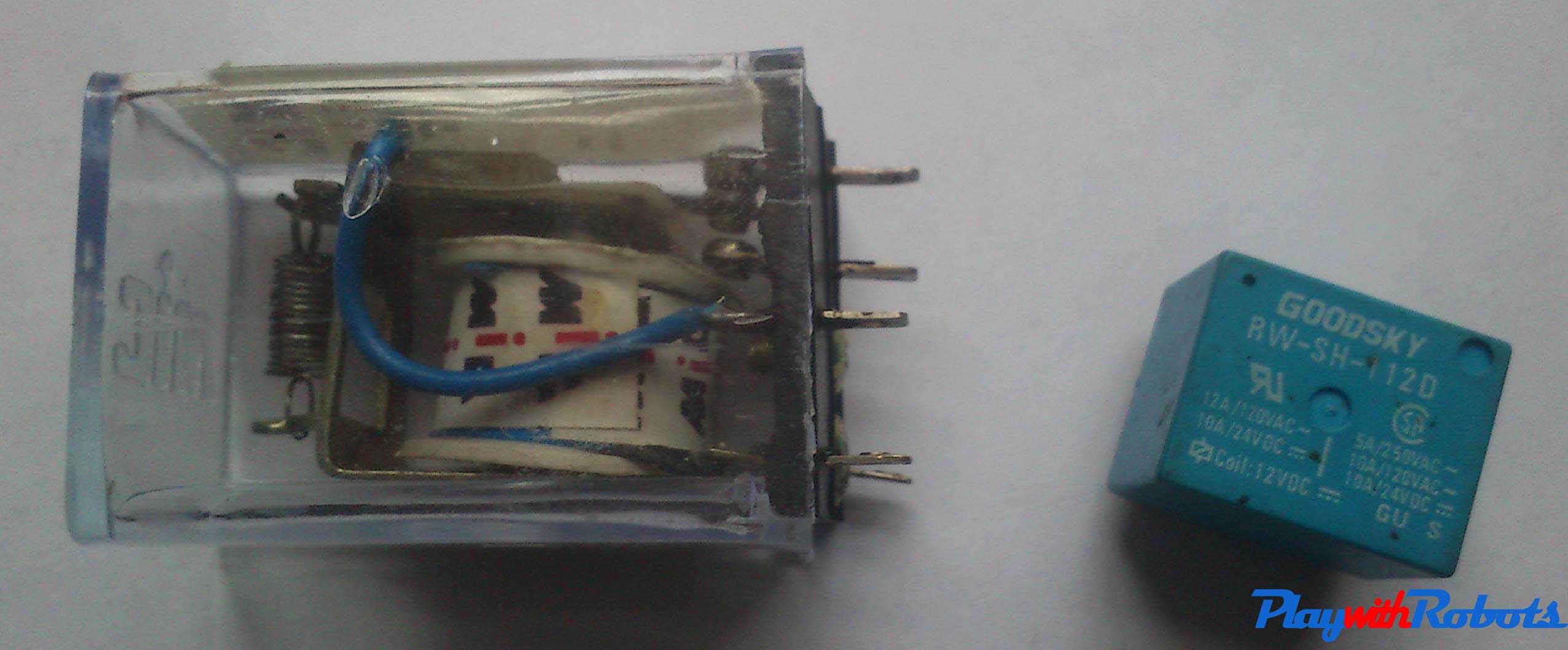
Working of relay
Working of a relay : Relays consist of a electromagnet, armature, spring and electrical contacts. The spring holds the armature at one electrical contact and as soon as a voltage is applied across the electromagnet, it coils the armature, changes its contact and moves to another electrical contact. The figure below describes its working.
Relays
Terms associated with relays:
- Normally Open (NO): contacts connect the circuit when the relay is activated; the circuit is disconnected when the relay is inactive.
- Normally Closed(NC): contacts disconnect the circuit when the relay is activated; the circuit is connected when the relay is inactive.
- Change Over (CO): Its the common contact.
- COIL: Its the electromagnet coil inside relay.
Relay ratings :
- Coil rating: Its the Voltage at which the coil gets fully activated. Some also have coil resistance mentioned on them. Relay coil voltage rated 6V and 12V are the most commonly available.
- Contact rating: It depends on whether AC or DC current is passing through the contacts. The blue colored relay shown in the start of this page has a rating of 12A at 120V AC , 5A at 250V AC and 10A at 24V DC.
Relay triggering circuit:
Depending upon a relay's coil rating, some may require current greater than 100mA. If an IC cannot provide this much current, a transistor is used as a switch to trigger the relay as shown below. Don't avoid the protection diode (D1 shown in circuit) as it will protect transistor from back emf induced in relay coil.
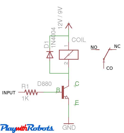
Relay triggering circuit
Switching speed of a relay is slow, around 10ms. Relays are used to drive an AC load from a small DC circuit, or to drive a high current consuming motors. Have you noticed a sound of tic -tic while car wiper is on, This is the sound of relay inside the car that drives the wiper motor.
Hope this was helpful to you! Any questions ?
More on PlaywithRobots
avr-tutorials
- Introduction to AVR microcontrollers
- Basic hardware and software required for AVR
- AVR fuse bits
- Input/Output Concept