As the name suggests an Advanced Line Follower Robot is just a Simple Line Follower Robot with a few extra features. It will move on a grid of black lines over white background in search of a white box and when the box is detected will raise an alarm and return to its original coordinate in the grid.
After reading this section completely you will be able to make one from simple components and play with it. Moreover we will make it modular so that it can be easily modified in future.
The main electronics/mechanical components that will be used in making this line follower robot are ATmega32/16 micro-controller, L293D IC, five sensors made using IR LED, photodiode and LM324 IC, acrylic sheet, General purpose board, Two DC motors and battery.
Chassis
The Chassis used for this line follower is same as the one we used in making Simple line follower robot. If you haven't made that, no worry just read the chassis part in the Simple line follower robot article.
Sensors
For this robot we will be using an IR transmitter and a receiver pair. If you don't know how to pair these two just read about it in Light sensors. We will be using four such pairs. The main advantage of using them over LDR is that they are more sensitive to IR light in comparison to the visible light therefore will work better under different light conditions.The overall circuit diagram of the sensor part and the logic used for the moving robot on a grid of black lines is shown below.
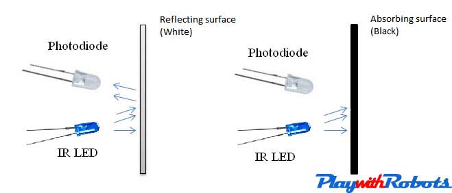
Sensor Principle
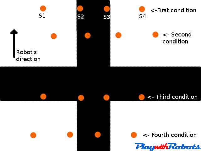
Logic
As described in above picture, the 2nd and the 3rd sensors are for line following and the 1st and the 4th sensors are for intersection detection.
- In the First condition, when the 2nd and the 3rd sensors are on the black surface the robot will move forward.
- In the Second condition, when the 2nd sensor is on the black line but the 3rd sensor is on the white surface, the robot will rotate left.
- In the Third condition, when the 1st and the 4th sensors are on the black line, an intersection is detected.
- In the Forth condition, when the 3rd sensor is on the black line but the 2nd sensor is on the white surface, the robot will rotate right.
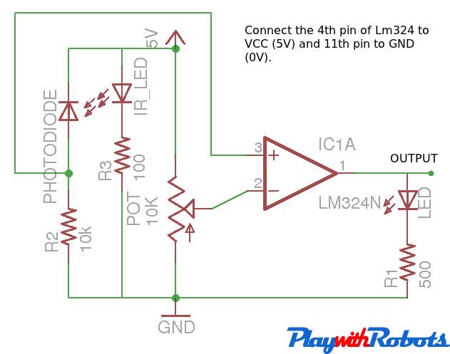
The complete circuit is divided into two parts. First, the IR LED and the photodiode pair is to be soldered on a small general purpose board. And a Comparator is to be soldered on another general purpose board, a little bigger than one used previously (Microcontroller circuit will also be soldered on this board later). Both boards are connected to each other with the help of connectors. Using two separate boards allows us to place the IR pairs below the robot for line sensing and the potentiometers above it, to make the adjustment of the threshold easier. Moreover it makes the circuit modular.
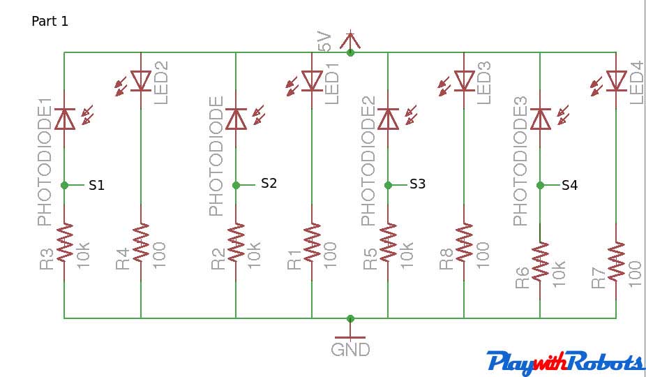
Circuit part 1
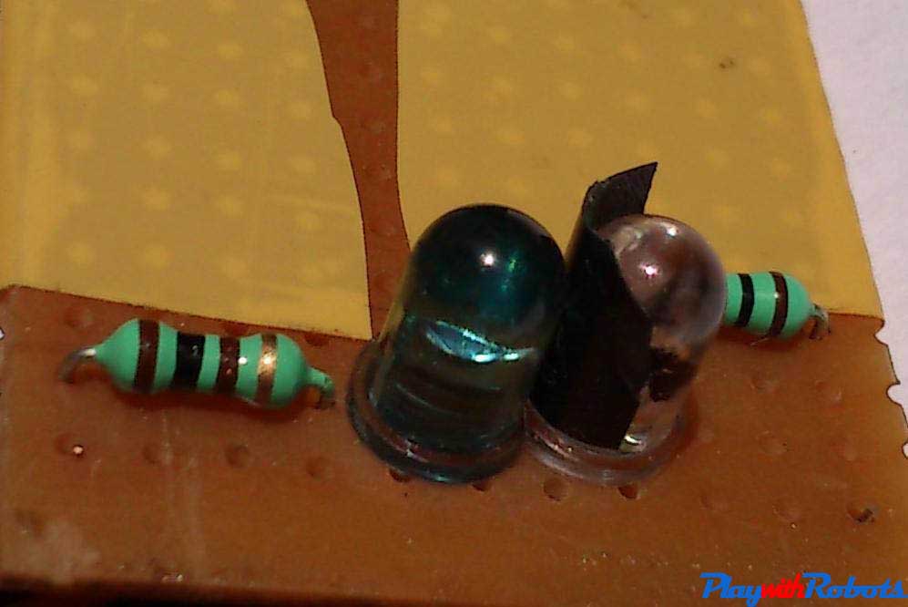
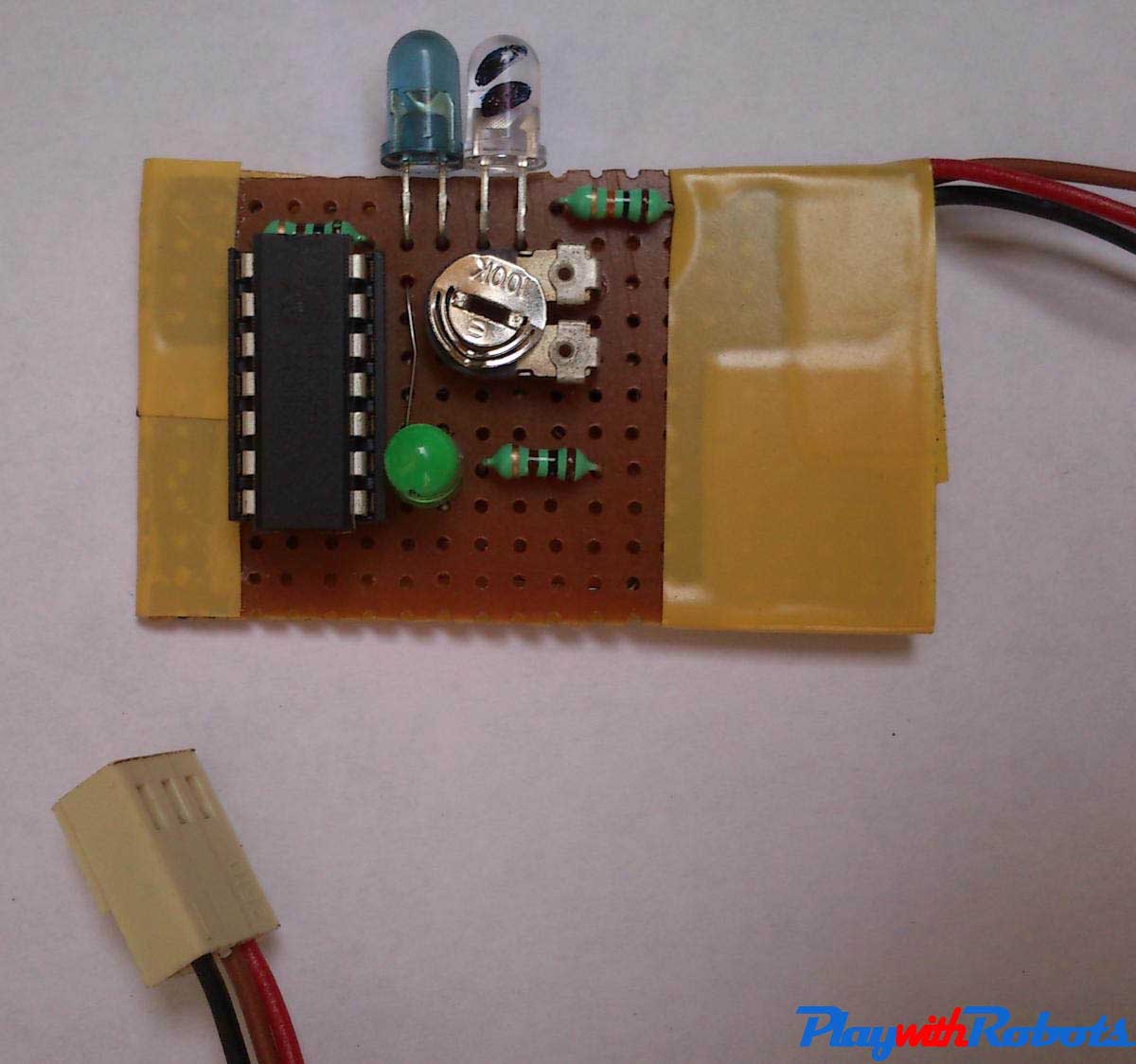
Given below is the picture of the above mentioned circuit in soldered form. The positioning of the IR LED and the Photodiode depends on the thickness of line. We will be using a black line of thickness 3 cm.
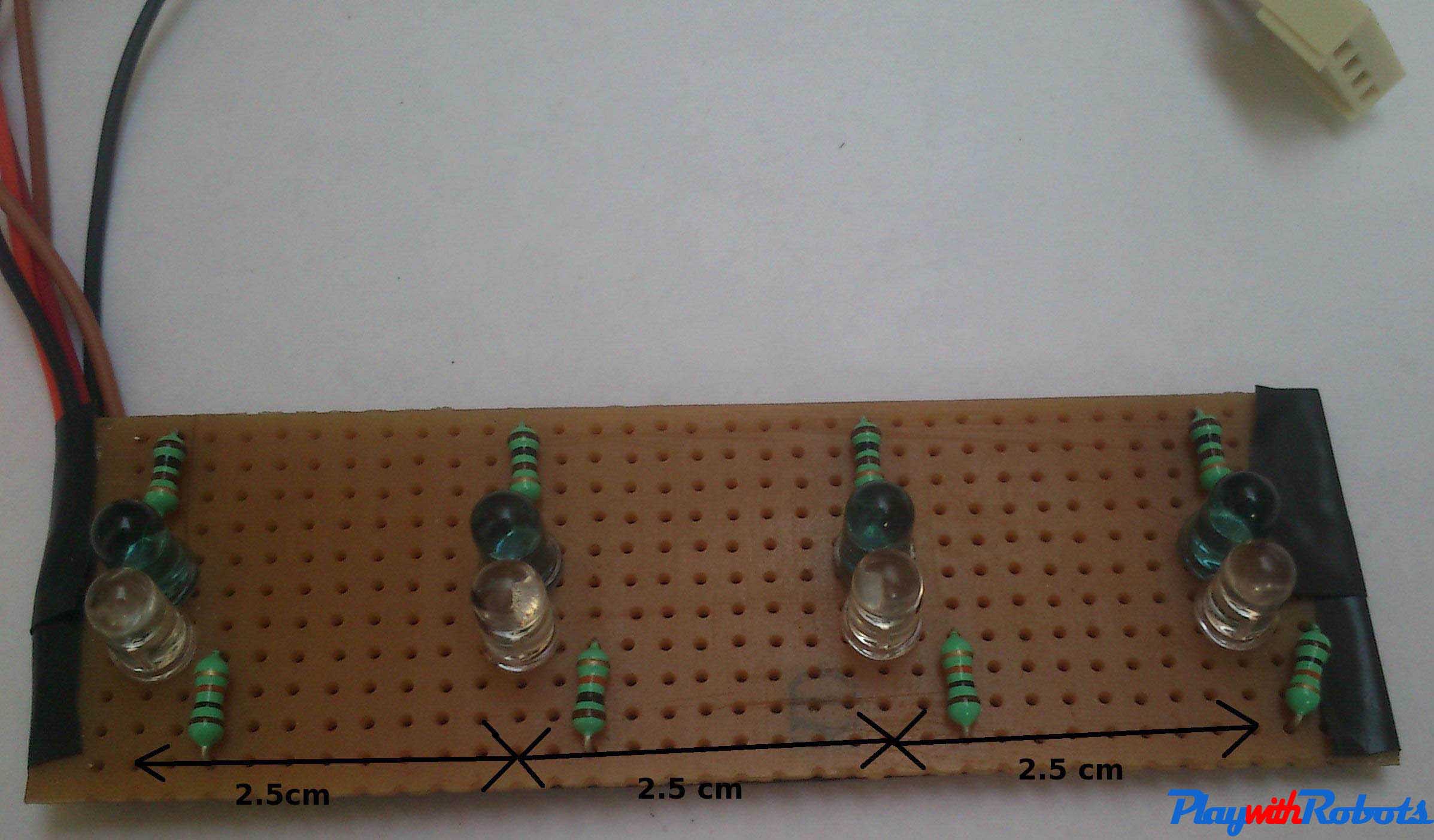
Soldered circuit
Now insert a small piece of black insulating tape in the gap between IR LED and Photodiode. This will insure that no direct IR rays from the IR LED falls on the Photodiode.
Covering
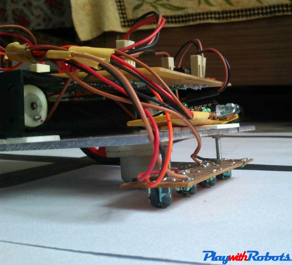
Placement of sensors plays a very important role in line sensing accuracy and the robot's movement. This circuit is fixed in front of the caster wheel below the robot and with the ground clearance of sensors as small as 2-3mm. Sensor circuit must be screwed tightly. See the picture below.
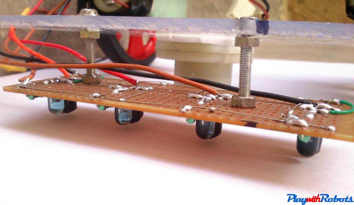
Sensor placement
Remaining circuit and AVR
The circuit diagram of part 2 is shown below. It may look a bit complex but will simplify as you read this page.
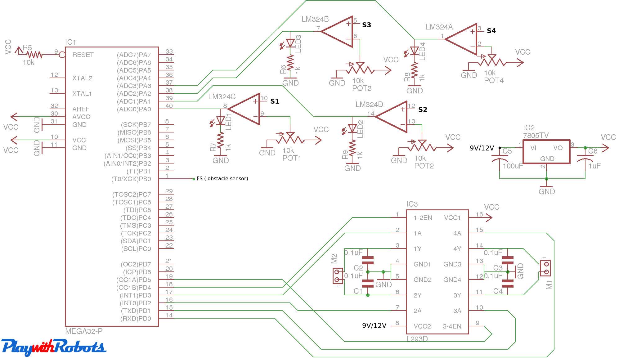
Circuit diagram part 2
The overall Block diagram of this robot's circuit is shown below
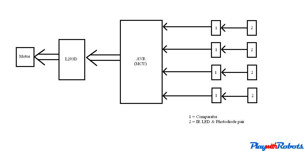
Block diagram
It is always better if you divide big circuits into small modules (Parts). Here, I have divided the circuit into 5 different modules (blocks) named IR LED photodiode pair, Comparator, AVR, L293D and motor .
- IR LED photodiode pair: They simply gives analog output to the Comparator.
- Comparator part: They takes the input from IR LED photodiode pair, compares it with the threshold set by potentiometer and gives a digital logic output to AVR .
- AVR: They takes input from 4 different comparators, processes it and outputs different control signals to L293D according to the sensors condition.
- L293D: They take input from the AVR and correspondingly give output to the motors. If you haven't used this IC yet for any project, you can read this quick and easy tutorial of motor driver circuits using L293D
- Motors: They revolve according to the input from L293D.
- Batteries: It is advisable to use Li-ion, or NiCd or NiMh or small lead acid batteries. Small cheap 9V batteries will drain completely within 4-5 minutes. If you are using 9V batteries make sure whenever output voltage of 7805 falls below 5V replace the battery.
Similarly there is a obstacle sensor which gives output to AVR .
Related articles on PlayWithRobots
The logic used for grid following is dividing each intersection in grid as a coordinate. Allocate a direction nomenclature according to which the robot moves. This will be cleared from the image below. You can download the code for ATmega32 microcontroller that i used here, but for information on basic concepts of AVR microcontrollers read the tutorials in AVR category.
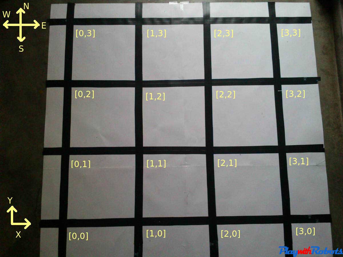
Logic
Now its time to make obstacle sensor for the bot!.
Obstacle sensor
This sensor will be used to detect obstacles in the robot's path, in our case the white block. The concept is same as that of line following sensors on reflection of light principal. We will be using IR LED and photodiode pair. To know more about them see this tutorial on light sensors.
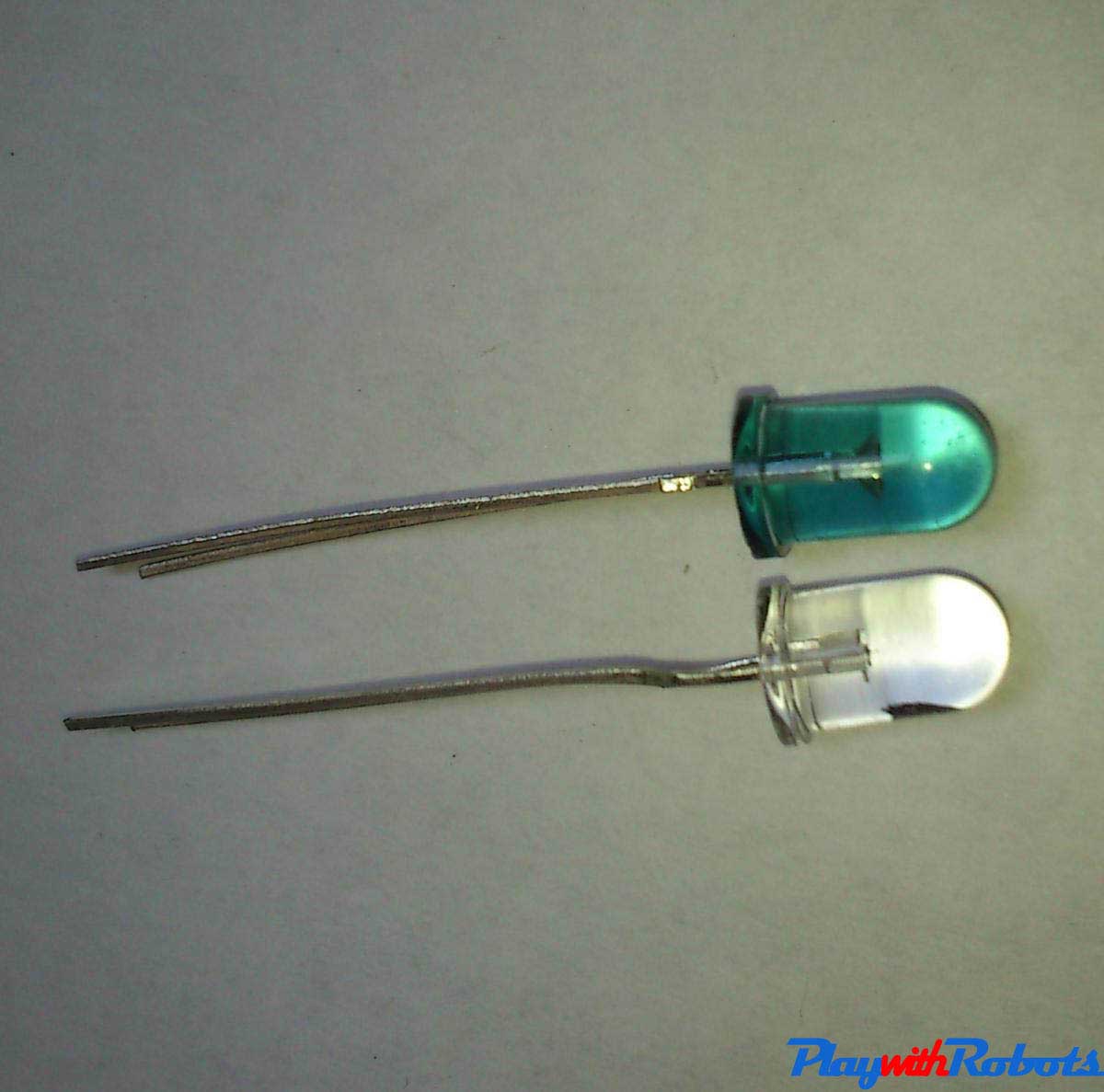
R LED Photodiode pair
Circuit
The complete circuit is to be soldered on a small general purpose board. The reason for not soldering this on the same board with our part2 circuit is that we want to make this sensor modular. If we want to use the obstacle sensor, just plug-in the 3 pin connector. If you are not on an obstacle detection grid just remove the connectors. In this way this can be used with any other robot. In my case a white block can be detected from a distance of 3cm to 7cm, which can be adjusted with the help of potentiometer.
Obstacle sensor
Wow! chassis, sensors, circuit all done, lets combine them all!.
Combining all
Now every part is ready, but each part is of no use unless we combine them all.
Sensors
Placement of sensors is very important. They are the robots eyes. Line following sensors must be fixed tightly in front of caster with a ground clearance of 2-4mm. If the sensors are loose, the signals may fluctuate during robot's motion. Take time in fixing sensor and adjusting the threshold for sensors as a little time spend here may save lots of troubleshooting later on.
Line sensor Placement
Obstacle sensor should be placed in front of the robot as can be seen in the final robot pictures at the end of this article.
Complete circuit
Place the remaining circuit on chassis and fix every connector to there respective places. There should be no loose wires hanging around, stick them with tape.
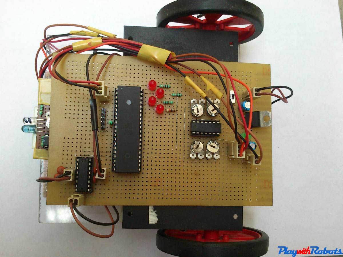
Complete Bot -1
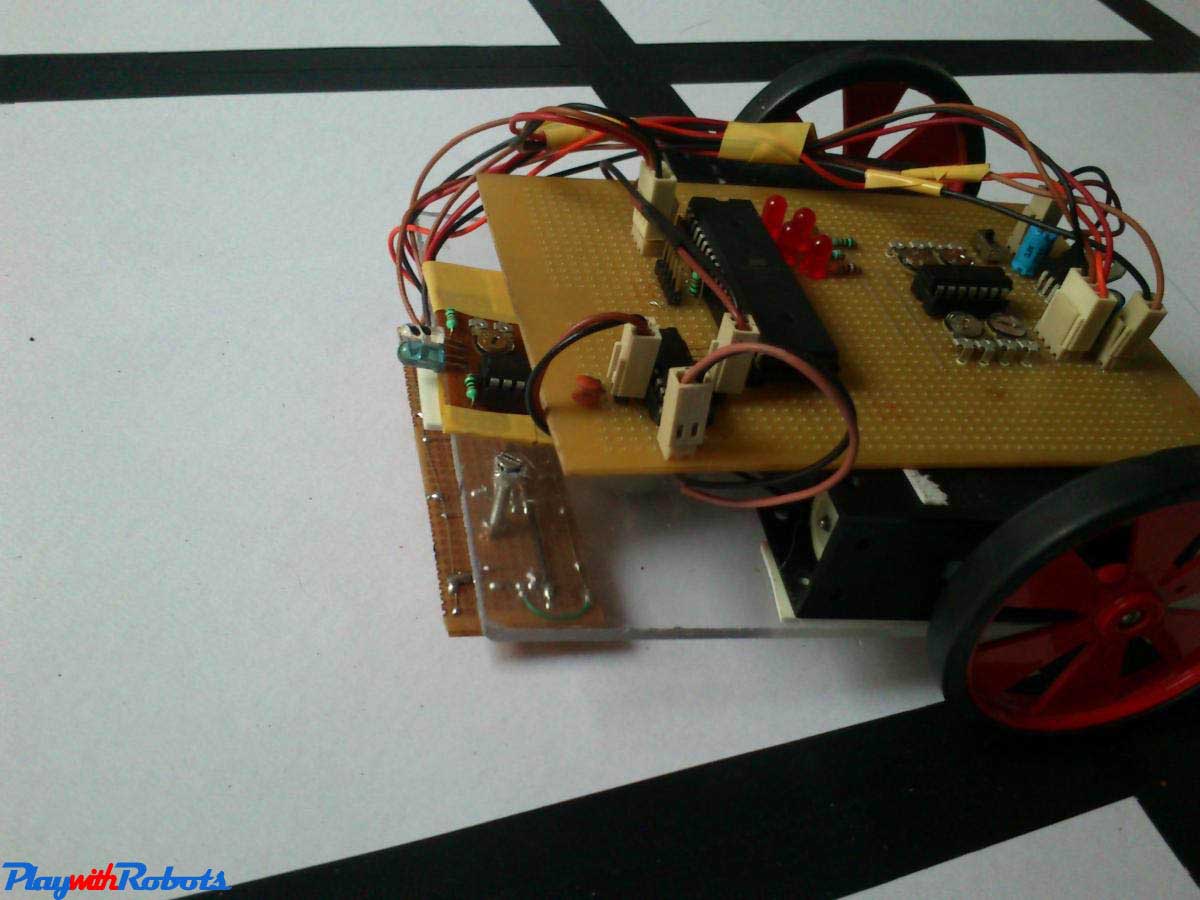
Complete Bot -2
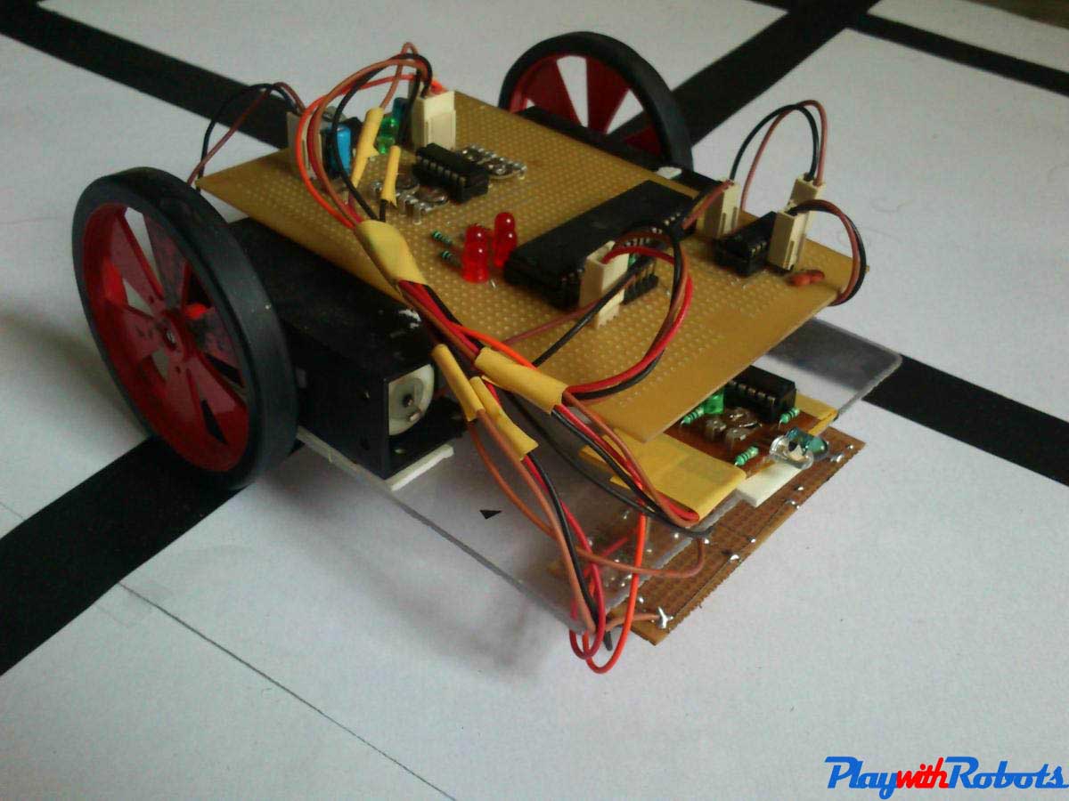
Complete Bot -3
Complete Bot -4
Arena
Obviously, without a grid the robot can't move. I made a sample arena on chart paper with black tapes though not the best one but still works . Arena must be neat and clean. The smallest marks here or there may fluctuate the sensors.
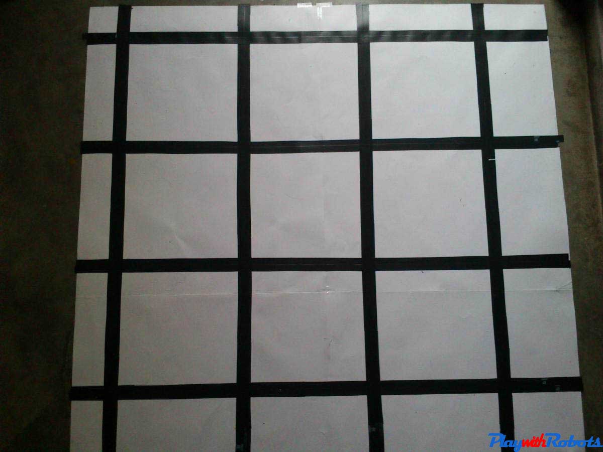
Arena
After adjusting all the sensors threshold and with some trail and error finally the robot will starts moving. :) See the video below.
Hope you liked the above tutorial. Subscribe to PlaywithRobots on facebook for more updates.
More on PlaywithRobots
avr-tutorials
- Introduction to AVR microcontrollers
- Basic hardware and software required for AVR
- AVR fuse bits
- Input/Output Concept