A robot that moves on an elevated surface by automatically detecting edges and avoiding the fall. !!
This tutorial is on making edge avoider robot can be seen in the video below:
Electronics
L293D, NE555 IC, one sensor made using IR LED, photodiode and LM324 IC
Mechanical
Acrylic sheet, General Purpose Board and two DC motors.
Concept:
Robot will be move forward as long as the sensor detects an surface under it. As soon as edge detector sensor goes out of the table, the robot will make an in-place rotation greater than 90 degree and then continue as per sensor value.
Chassis:
Its chassis is similar to the one made for simple line follower robot. You can make exactly the same one, picture of complete chassis is attached below:
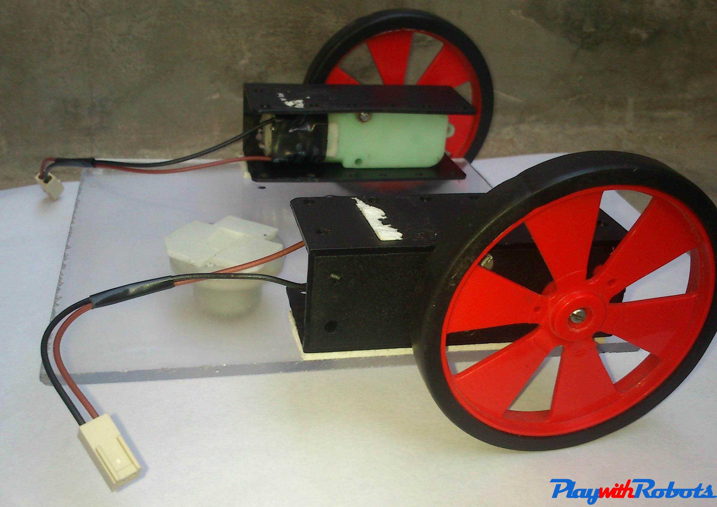
Chassis complete
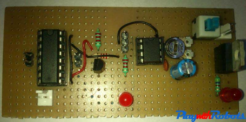
Circuit:
I tried to make it as simple as possible. Its circuit is divided into two parts, one is sensor part and other is logic and motor driver part.
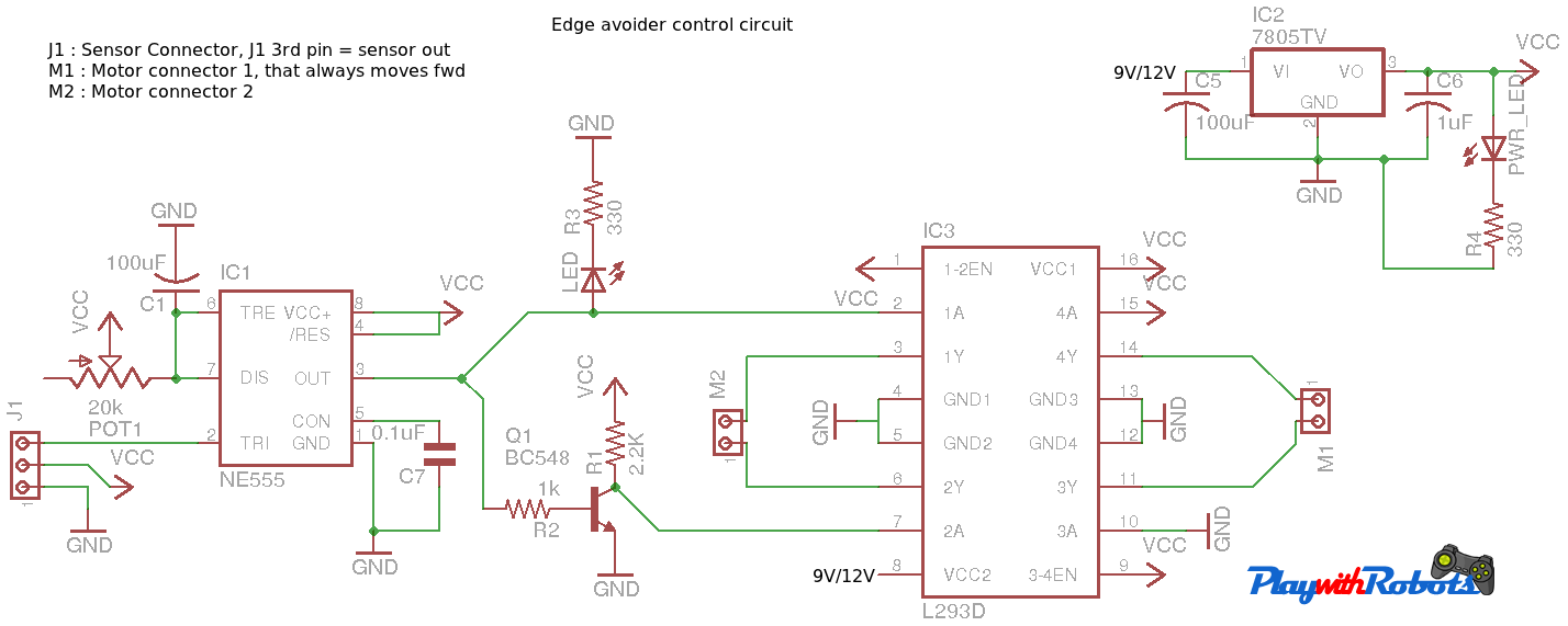
Circuit Diagram - control part
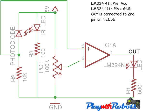
Circuit Diagram- sensor part
Now its sensor will be placed write in front of the robot. So the sensor circuit will be soldered on a small General Purpose Board and the remaining circuit will be soldered on other General Purpose Board and both will be connected with the help of 3 pin connector.
The sensor circuit for this robot is similar to that of object detection sensor made earlier for Advance line follower robot. As said earlier, while making that sensor, that we will make it modular so that it can be used with any other robot, now sticking to my words I'm using that board for this robot as edge detector sensor, I haven't made a new circuit. This is the benefit of making modular circuits. You can make exactly the same sensor circuit, it will look like the picture below:
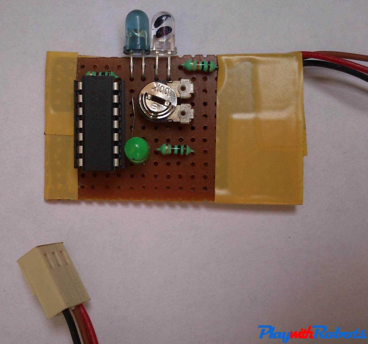
Edge Detector sensor circuit
L293d is used for motor driver circuit, if you haven't used this IC yet for any project, you can read this quick and easy tutorial of motor driver circuits using L293D
The figure below shows my soldered circuit of logic and motor driver part. A 3-pin connector is visible in the image (left of 555 timer) , which will be used for connecting this circuit and sensor circuit.
Soldered circuit -2
Logic:
Now a question may arise that what is the use of NE555 timer in this circuit? The answer is NE555 is used as a monostable vibrator i.e. once triggered (Voltage at pin 2 falls below Vcc/3), a high logic pulse of specific time will appear on the output pin i.e. pin 3. The width of this pulse depends on the Resistance R (between 7th pin and Vcc) and capacitor C1 by the equation
Related articles on PlayWithRobots
T (pulse width in seconds) = 1.1RC1
Now I have connected a variable resistance of 20K in place of R so that we can adjust the pulse width. So the maximum pulse width possible from this combination is 2.2sec.
Till now, we are able to generate a pulse of fixed time whenever sensor comes out of the table. We will be using this pulse to reverse the direction of one motor in order to make a in-place rotation for certain duration. For this a transistor is used as NOT gate. Adjust the duration of this in-place rotation by changing the pulse width such that when edge is detected angle of rotation should be in-between 110-150 degree.
NOTE: When powered on, the robot will make an in-place rotation while placed on table and after that will continue normally.
Combining all:
Now sensor, motor driver circuit, and chassis are ready so lets combine them all!.
Sensor placement is important, fix it in the front of the robot by extending robot chassis. During robot's motion sensor may vibrate, adjust the threshold and height of sensor such that its output will not fluctuate. The picture below will give you an idea.
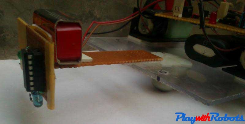
Sensor Placement
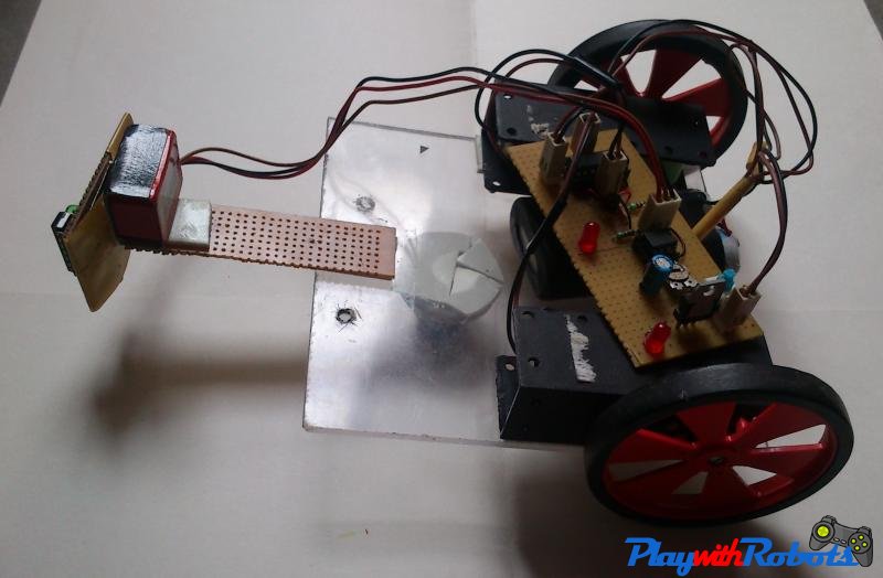
Complete bot
The video once again !!
Hope you liked the above tutorial. Subscribe to PlaywithRobots on facebook for more updates.
More on PlaywithRobots
avr-tutorials
- Introduction to AVR microcontrollers
- Basic hardware and software required for AVR
- AVR fuse bits
- Input/Output Concept