This tutorial is on making sensor circuit using :
Light Dependent Resistors (LDR)
As the name suggests, resistance of a LDR depends on the amount of light incident upon it. Normally its resistance is around 1 mega ohms (in Dark) and when light falls on it, the resistance drops to a few kilo ohms. It is a bilateral device.
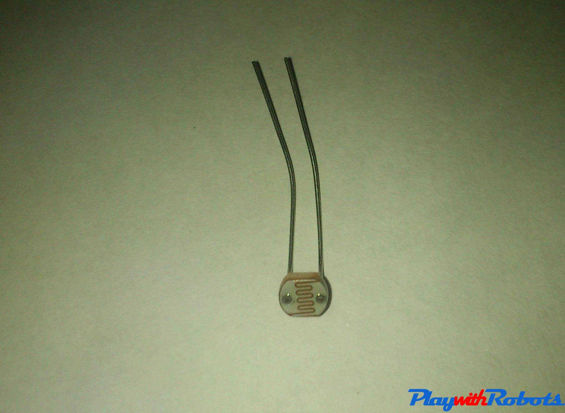
LDR
The video below shows how the resistance varies.
How to use LDR?
Using Transistor
The circuit works on the principle of wheatstone bridge. When light falls on LDR, its resistance decreases and current in the LDR's branch increases which makes the transistor biased and the LED will glow. The variable resistor in series with LDR helps to set the threshold level. Adjust the variable resistor such that in absence of light voltage BE should be less that 0.5 Volts. When light intensity increases this voltage would increase and when it is greater than 0.8 Volts LED will glow brightest. To reverse the process (absence of light = LED glow), just exchange the position of LDR and variable resistance, and adjust variable resistance such that in presence of light Vbe is less than 0.5 Volts.
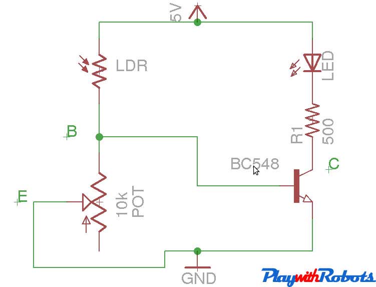
LDR circuit
Using Comparator circuit
The principle of this circuit is also wheatstone bridge. But instead of using a transistor we will be using a operational amplifier IC, like LM324. It contains 4 independent Operational amplifiers. For more information you can always consult its datasheet. Its working in comparator configuration is described below.
Whenever voltage V1 if greater than Voltage V2 the output is high i.e (Vcc -1.5V). And whenever V1 is less than V2 the output is low i.e 0V provided V1,V2 and Vcc are always withing desired rating as mentioned in IC's datasheet. For example if Vcc=5V, V1=1.54V, V2=1.12V then Vout = 3.5V. (A high level for most of digital ICs and microcontrollers including ATmega32 microcontroller). Moreover we would prefer this circuit while interfacing light sensors with other digital ICs.
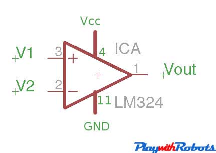
Comparator
The circuit diagram of using LDR with comparator is shown below. Using Potentiometer, set the voltage at pin 2 just less than voltage on pin 3 under the light conditions you want LED to switch off. Now as soon as more light will fall on LDR, Voltage at pin 3 will become more and LED will glow!.
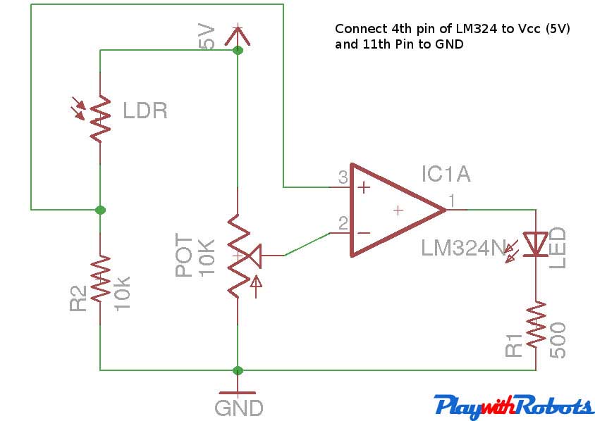
Circuit diagram
See how the above circuit works. ( This video is of transistor circuit but comparator circuit will also looks same in video! ) :
Two copies of above circuit were used to make a simple line follower robot!.
Photodiode (IR receiver)
Unlike LDR that works in visible region of light, photodiodes have more sensitivity to the infrared region. They are used with IR LEDs instead of normal LEDs. When infrared light is absorbed by a photodiode, the number of free electrons and electron holes changes and raises its electrical conductivity. They are unilateral and work in reverse bias.
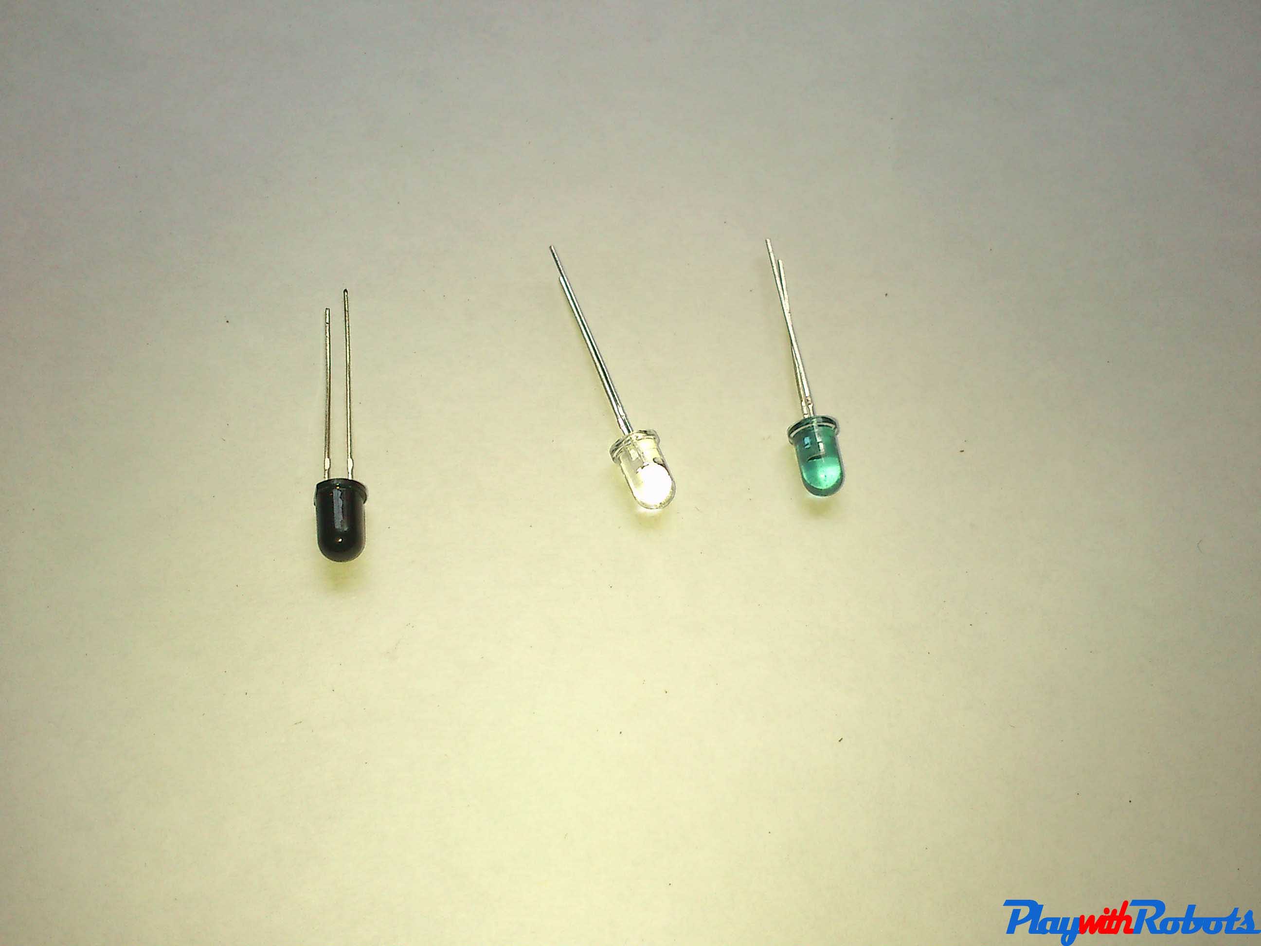
Filtered Photodiode, Photodiode, IR LED
How to use photodiodes?
Using transistor
The circuit works on the principle of wheatstone bridge. When IR rays falls on a photodiode, its conductivity and current in the photodiode's branch increases which makes the transistor biased and the LED glows. The variable resistor in series with photodiode helps to set the threshold level. Adjust the variable resistor such that in absence of IR, voltage BE should be less that 0.5 Volts. When IR intensity will increase this voltage would increase and when it is greater than 0.8 Volts LED will glow brightest. To reverse the process (absence of IR rays = LED glow), exchange the position of photodiode and variable resistance, and adjust variable resistance such that in presence of IR rays Vbe is less than 0.5 Volts. IR Led is used to produce IR rays. Human eyes can't see IR rays so in order to check that IR LED is glowing or not after making the circuit see IR Led under a digital camera.
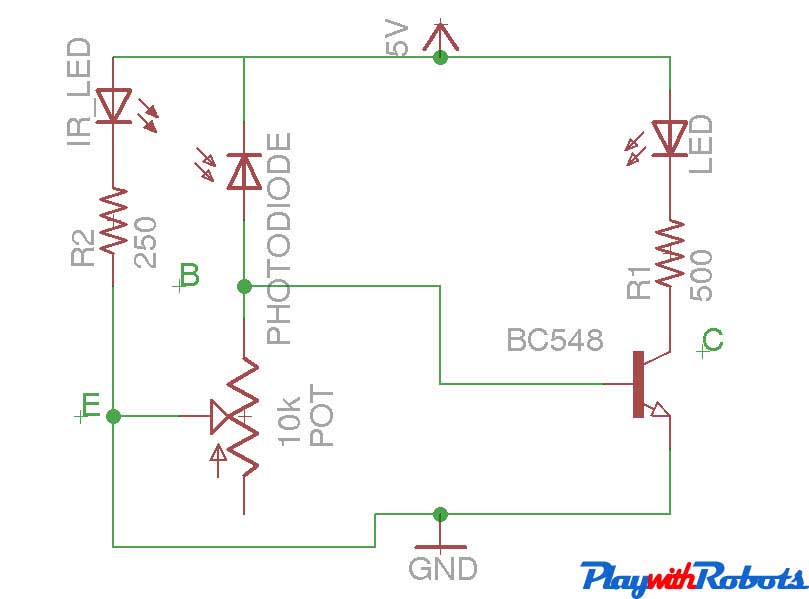
Circuit diagram
Using Comparator circuit
The principle of this circuit is also wheatstone bridge. But instead of using a transistor we will be using a operational amplifier IC, like LM324. It contains 4 independent Operational amplifiers. For more information you can always consult its datasheet. Its working in comparator configuration is described below.
Comparator
Whenever voltage V1 if greater than Voltage V2, the output is high i.e (Vcc -1.5V). And whenever V1 is less than V2, the output is low i.e 0V provided V1,V2 and Vcc are always withing desired rating as mentioned in IC's datasheet. For example if Vcc=5V, V1=2.54V, V2=1.12V then Vout = 3.5V. (A high level for most of digital ICs and microcontrollers, including ATmega32 microcontroller). Moreover we would prefer this circuit while interfacing light sensors with other digital ICs.
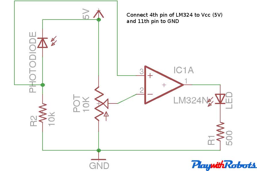
Circuit diagram
See how the above circuit works: (This video is of transistor circuit but comparator circuit will also looks same in video! ) :
Four copies of the photodiode circuit using comparator were used in making line sensors for Advance line follower robot!.
Hope this was helpful to you! Follow PlaywithRobots on Facebook for more updates.
More on PlaywithRobots
avr-tutorials
- Introduction to AVR microcontrollers
- Basic hardware and software required for AVR
- AVR fuse bits
- Input/Output Concept